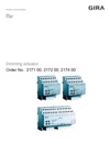
Dimming actuator, 2-gang for KNX 2 x 300 W/VA

Specification
Item no.
Room
Quantity
EAN
PU
PS

DRA
2172 00
4010337082217
1
Price system (PS) not equal to 1, 14 = reduced discount.
Note: For legal reasons, some products are not available in certain countries.
DRA
EAN 4010337082217
Item no. 2172 00PU 1
PS
Price system (PS) not equal to 1, 14 = reduced discount.
Note: For legal reasons, some products are not available in certain countries.
Optional accessories
Features
- Dim actuator with integrated bus coupler.
- Switching and dimming of light bulbs, HV halogen lamps, dimmable HV-LED lamps, dimmable compact fluorescent lamps, dimmable inductive transformers with LV halogen or NV-LED lamps, dimmable electronic transformers with LV halogen or NV-LED lamps.
- Automatic or manual selection of dimming principle according to load.
- Idle-state, short-circuit, and excess temperature-proof.
- Manual operation of the outputs independent of the bus (building site operation also possible).
- Building site operation: Outputs can be operated manually without bus voltage with operating voltage only.
Functions
- Independent control of the dimming channels.
- Central switching function for control of all dimming channels.
- Delay for actively transmitted feedback messages following bus voltage recovery.
- The load type can be specified and the dimming principle defined: Universal (with automatic calibration procedure), electronic transformer/LV LED (capacitive/phase cut), conventional transformer/LV LED (inductive/phase cut), HV LED (phase cut) or HV LED (phase cut).
- Feedback for "switching" and "brightness value".
- Dimmable brightness range can be set.
- Dimming behaviour and dimming characteristics can be parameterised.
- Switch-on behaviour for a relative dimming command can be parameterised.
- Bulb-saving switch-on and switch-off
- Automatic setting and scaling of the dimmable brightness range when using universal power boosters.
- The performance of a dimming channel in the "OFF" state during reception of a relative dimming command can be parameterised (switching and dimming or no response).
- Alarm telegrams for short circuit, overload, and load failure.
- Feedback of connected load type.
- Block function or forced setting function can be parameterised for each output.
- Time functions (switch-on or switch-off delay, staircase light function).
- Staircase light function with advance warning function via time-controlled reduction of lighting or activation of permanent lighting.
- Linking function and up to eight scenes per dimming channel possible.
- Elapsed-hours meter for recording switch-on time.
- Reactions after bus voltage failure and recovery can be set.
Technical data
| KNX medium | TP256 |
| Rated voltage | AC 110 to 230 V, 50/60 Hz |
| Max. connected load (AC 230 V) per channel | |
| Light bulbs | 20 to 300 W |
| HV halogen lamps | 20 to 300 W |
| Wound electronic transformer | 20 to 300 VA |
| Tronic transformer | 20 to 300 W |
| Wound transformer with NV-LED | 20 to 100 VA |
| electronic transformer with NV-LED | typically 20 to 100 W |
| HV LED lamps | typically 3 to 60 W |
| Compact fluorescent lamp | typically 3 to 60 W |
| Connected load (AC 110 V) per channel | |
| Light bulbs | 20 to 150 W |
| HV halogen lamps | 20 to 150 W |
| Wound electronic transformer | 20 to 150 VA |
| Tronic transformer | 20 to 150 W |
| Wound transformer with NV-LED | 20 to 50 VA |
| electronic transformer with NV-LED | typically 20 to 50 W |
| HV LED lamps | typically 3 to 30 W |
| Compact fluorescent lamp | typically 3 to 30 W |
| Connections | |
| KNX | Connection and junction terminal |
| Load | Screw terminals |
| Connection cross section | Max. 4 mm² |
Notes
- Power expansion using Gira power boosts.
- Installation on DIN top-hat rail.
- VDE approval in accordance with EN 60669-1, EN 60669-2-1.
Scope of delivery
- Connection and junction terminal for KNX included with delivery.
Dimensions
| Modular widths (MW) | 4 |
More links
Gira dimming actuators for KNX
More


Dimming actuator 1-/2-/4-gang (I04)
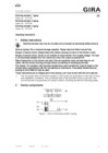
Operating instructions.
Operating instructions.
Dimming actuator 1-/2-/4-gang (I04)
Technical documentation.
Technical documentation.
Dimming actuator, 1-, 2-, 4-gang (I04)
Product database from ETS3.0d.
Product database from ETS3.0d.
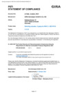
Dimming actuator, 2-gang for KNX 2 x 300 W/VA
PSTI Statement of Compliance
PSTI Statement of Compliance
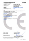
Dimming actuator, 2-gang for KNX 2 x 300 W/VA
EC Declaration of conformity
EC Declaration of conformity