Control unit 1 – 10 V, 4-gang with manual actuation for KNX

Specification
Item no.
GBP/unit
excl. VAT:
excl. VAT:
Room
Quantity
EAN
PU
PS

DRA
2224 00
233.87
4010337018858
1
26
Recommended retail price, prices valid for United Kingdom as of the stated date 01/26
Price system (PS) not equal to 1, 14 = reduced discount.
DRA
EAN 4010337018858
Item no. 2224 00PU 1
GBP 233.87PS 26
Recommended retail price, prices valid for United Kingdom as of the stated date 01/26
Price system (PS) not equal to 1, 14 = reduced discount.
Optional accessories
Accessories
Features
- The control unit switches and dims electrical devices that feature a 1–10 V interface.
- Five device configurations can be selected. This leads to the assignment of four individually-controllable dimming channels to the switching outputs (e.g. four dimming channels are assigned to one switching relay to control a RGBW light).
- Relay outputs that are not associated with a dimming channel can be used as freely-acting switching actuator channel.
- Reactions in case of bus voltage failure and restoration can be set following an ETS programming process.
- Manual actuation of the outputs independently of the bus with mechanical switching position indicator.
- Delay for actively transmitted feedback messages following bus voltage recovery.
- Logical linking function configurable per channel.
- Up to three central switching functions for the joint control of all dimming and switching channels.
- Switch-on times of the relay outputs can be recorded and evaluated by the elapsed-hours meter.
- Group feedback of all switching conditions possible.
Dimming channels
- Four individually-controllable dimming channels.
- Feedback on switching condition and brightness value.
- Dimmable brightness range can be set.
- Dimming behaviour and dimming characteristics can be parameterised.
- Soft switch-on and soft switch-off function
- Block function or forced setting function can be parameterised.
- Time functions (switch-on delay, switch-off delay, staircase light function). With the staircase light function, the reaction at the end of the switch-on time can be configured.
- Inclusion of a dimming channel in up to ten scenes is possible.
- The burning-in function allows for the commissioning of new fluorescent lamps prescribed by lighting manufacturers.
Switching actuator operation (optional)
- Independent switching of switch outputs A2 to A4.
- NO contact or NC contact operation.
- Feedback from the switching condition.
- Block function or forced setting function can be parameterised.
- Time functions (switch-on, switch-off delay, staircase light function - also with advance warning function).
- Can be integrated in the light scenes. Up to ten internal scenes per switching output are programmable.
- Cyclical monitoring of incoming switching telegram is configurable.
Technical data
| KNX medium | TP256 |
| Relay | |
| Quantity | 4 |
| Contact | 1 x zero-voltage NO contact each, flip-flop |
| Control outputs | |
| Control voltage | 1 to 10 V |
| Control current per output | max. 100 mA |
| Cable length | max. 500 m with 0.5 mm² |
| Switch outputs | |
| Switching voltage | AC 250/400 V |
| Switching current 230 V AC1 | 16 A |
| Switching current 230 V AC3 | 10 A |
| Switching current 400 V AC1 | 10 A |
| Switching current 400 V AC3 | 6 A |
| Fluorescent lamps | 16 AX |
| Lamp loads | |
| Light bulbs | 3680 W |
| HV halogen lamps | 3680 W |
| Wound electronic transformer | 2000 VA |
| Tronic transformer | 2500 W |
| Fluorescent lamps T5/T8 | |
| Uncompensated | 3680 W |
| parallel compensated | 2500 W/200 µF |
| Duo-circuit | 3680 W/200 µF |
| Compact fluorescent lamps | |
| Uncompensated | 3680 W |
| parallel compensated | 2500 W/200 µF |
| Mercury-vapour lamps | |
| Uncompensated | 3680 W |
| parallel compensated | 3680 W/200 µF |
| Ambient temperature | -5 °C to +45 °C |
| Connections | |
| KNX | Connection and junction terminal |
| 1 – 10 V | Screw terminals |
| Load | Screw terminals |
| Connection cross section | Max. 4 mm² |
Notes
- Electronic ballasts generate very high current spikes. For this reason, use a switch-on current limiter or a separate load contact for with greater loads.
Scope of delivery
- Connection and junction terminal for KNX included with delivery.


Control unit 1 – 10 V, 4-gang with manual actuation for KNX
PSTI Statement of Compliance
PSTI Statement of Compliance
Control unit 1 – 10 V, 4-gang with manual actuation for KNX
EC Declaration of conformity
EC Declaration of conformity
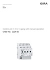
Control unit 1 – 10 V, 4-gang with manual operation
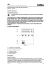
Operating instructions.
Operating instructions.
Control unit 1 – 10 V, 4-gang with manual operation
Technical documentation.
Technical documentation.